3D-CFD modelling in urban drainage systems
Mattias Deller, 17 August 2020
Hydraulic evaluation and optimization of a union drop shaft
When designing elements of urban drainage systems, analytical approaches and 1D-simulations are often applicable only to a limited extend, the space is limited and existing sewage pipes must be taken into account. Using three-dimensional computational fluid dynamics (3D-CFD), designed or existing structures can be validated at the design and maximum discharge capacities, and as a result, the structures can be optimized. Overall, such analysis help to minimize the design uncertainties and select the best solution with the existing limitations.
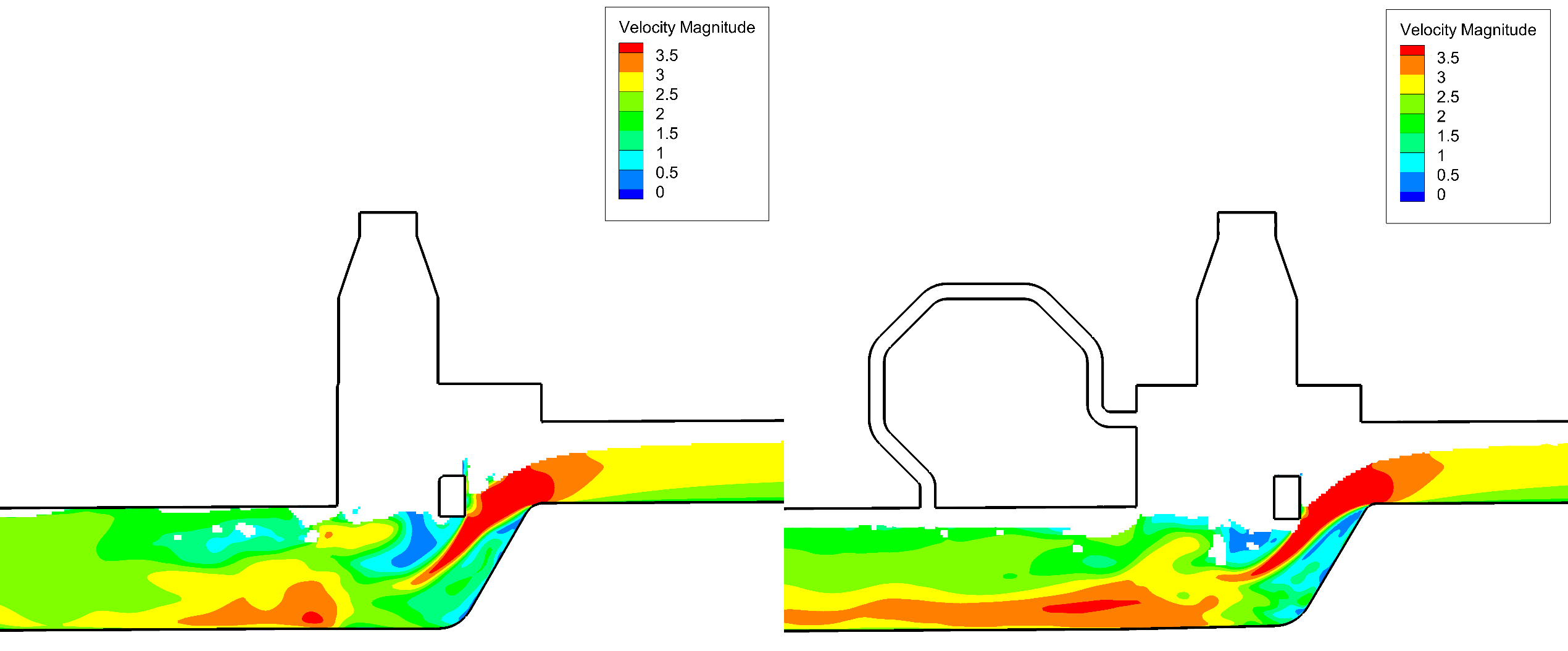
Next is an example of a drop shaft junction modelling, which contains two inflows (DN800 and DN600 pipes) and unites the outflow into an egg shape pipe. Both inflows must overcome a height difference of 0.6-1.2 m when entering the structure. TK CONSULT AG was commissioned to perform 2-phase simulations (water, air) to evaluate and optimize the hydraulics of the complex flow in the structure. The required design discharge capacity was used for the inflow. The simulation showed that in the transition from the union structure to the egg profile, the degree of filling almost reached 100% for the initial geometry. Hence, the flow pattern from the 3D-CFD simulation was used to improve the confluence of the two inflows, by applying a small enlargement of the shaft and a better confluence angle, the degree of filling was reduced by 20%.