3D-CFD simulation of a rainwater basin with an upstream drop shaft
Mattias Deller, 22. February 2021
Hydraulic testing of the renovation work on a rainwater basin and the construction of a new drop shaft using a 3D-CFD simulation.
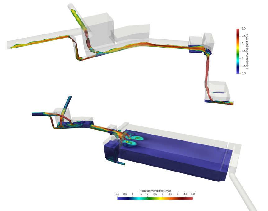
As part of the renovation of a cantonal road, construction synergies should be used to expand the capacity of the sewer system. The maximum inflow capacity to the rainwater basin should be increased by a factor of four. This enables an increase of the catchment area as well as a future usage of the rainwater basin as an emergency basin. Various renovation measures are necessary to ensure that the rainwater basin meets the required standards and has sufficient performance. To achieve the most cost-effective conversion possible, several hydraulic solutions were planned, which are difficult to dimension with analytical calculations. To overcome the height difference between the new pipes and the rainwater basin, a new drop shaft is to be built upstream of the rainwater basin. The testing of the hydraulic functionality of the reconstruction measures for the rainwater basin and the drop shaft, was carried out using a 3D-CFD simulation. By using a 2-phase-model (water and air), it was possible to check the hydraulics and the ventilation system within the structures.